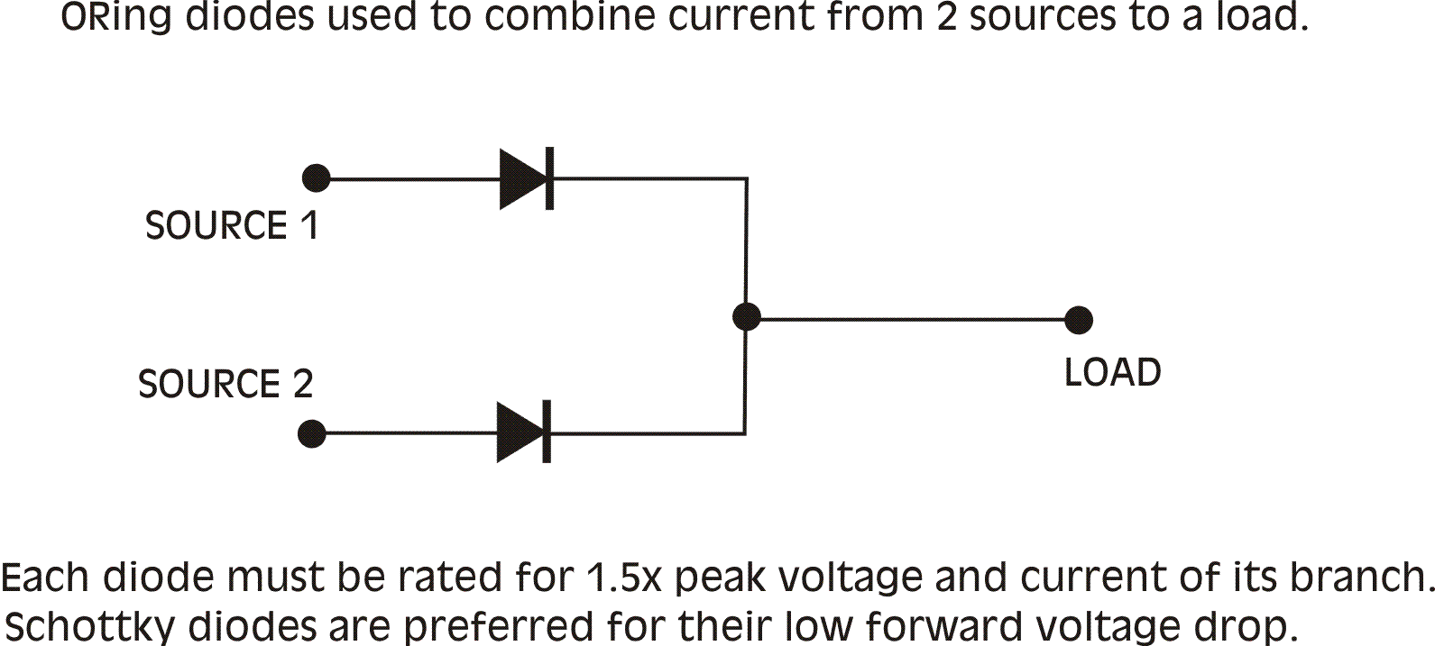
Connecting Switching power supplies in parallel is possible if certain precautions are observed.
1. Use ORing diodes
These are diodes connected to form a logic OR function.

This is a simple OR gate. If either the top leg, or the bottom leg, or both,
are high, the output will be high.
If both inputs are low, the output is low.
In the analog world, the higher of the 2 input voltages will be passed to the
output, and the lower one will be ignored.
More importantly, the higher voltage leg will not push current back into the
lower voltage leg. And each voltage source will be unaware of the presence of
the other.
Any silicon rectifiers could be used in the above function, but if substantial currents will be present, Schottky diodes are preferred, because their lower voltage drop will dissipate less power and heat. The ratings should be 1.5 times the maximum current and voltage expected in each branch. In the case of the lambda, you may assume 4A peak if the SMPS is modified for current, 2.5A otherwise, which requires 6A or 4A Schottkys , respectively. For voltage, you must assume the entire branch voltage with respect to ground as worst case, so, for 45V sources, 70V Schottkys will be needed. If one supply should come on before the other on applying power, then the latent branch diode will see the full branch voltage across its terminals.
If you do nothing else, do Nr 1 above. These suggestions are presented in order of importance. The ORing diodes are imperative for parallelling power supplies, and cannot be skipped. They are required for safety, and all they do is keep you from making major blunders. To refine your setup, however, you can go further, and may stop at whatever level of difficulty you are comfortable with.
2. Closely trim voltages
Trim the voltages from each power supply to be as closely matched as possible. If one SMPS puts out 100mV more than the other, then the higher SMPS will provide all the current to the load alone, until its voltage drops sufficiently (from loading) to equal the lower voltage branch, at which time the sibling supply will start to contribute current also. If it takes 0.5A draw to cause a 100mV drop in output voltage, then the higher voltage supply will always be delivering 0.5A more than the lower one. Unequal load sharing does not make efficient use of available power.
3. Share the control loop
Each SMPS does its own work of sampling the output voltage, and making
recommendations to the PWM controller on how to drive the power MOSFET.
It makes sense that for two supplies working together, the recommendations
should be identical, but they may not be. To ensure that they are, pins Nr 2 of
each SMPS controller chip (UC3842) could be tied together through a 100-500 ohm
resistor.